Networking and Communication
Table of content:
1 - SPI wired2 - I2C wired
3 - Serial wired
4 - Serial wireless
In this week of networking and communication, we had to explore different networking and communication protocols. I'll explain some of the
communication protocol i tried during the electronics production, electronics design, output device and interface and application week.
SPI | wired
The Serial Peripheral Interface (SPI) is a synchronous interface which means the data sent are synchronized and that
data bits are transferred one by one at regular intervals of time set by a reference clock line. SPI is a full duplex communication
which means the SPI device can either be configured as master or secondary device. For the comunication or to send/receive data, SPI protocol
requires 6 wires:
MISO
MOSI
SCK
CHIP SELECT(reset)
GROUND
VCC
.
In the week of electronics design i made a hello world board with attiny44 IC and in the week of output device I made another board with attiny44
IC too, and to program those board you need a programmer. In the electronics design week i made a fabISP with attiny45 IC. There is SPI communication
between the attiny44 board and the fabISP while programming. While programming you need to connect MISO-MOSI-SCK-RESET-GROUND-VCC pins of the
fabISP with the MISO-MOSI-SCK-RESET-GROUND-VCC pins of the attiny44 boards,
Then you need to connect the fabISP with your PC and upload the sketch,
The sketch will be uploaded to your attiny44 board via fabISP. This was an example of SPI communication protocol.
I2C | wired
I2C, short for inter-imtegrated circuits is a type of synchronous serial communication protocol which means that data bits are transferred one
by one at regular intervals of time set by a reference clock line. I2C protocol requires just two common wires to control any device on I2C
network which are Serial clock(SCL) and Serial data(SDA). The data to be transferred is sent through the SDA wire and is synchronized with the
clock signal from SCL. SDA is the line for the master and secondary to send and receive data. SCL is the line that
carries the clock signal. I2C is a half duplex communication.
In the week of input device, i made a board with attiny1614 IC on which i tried usinng 0.96 inch OLED, which operates on I2C protocol. Each
device has a unique I2C address and you need to define that address in the sketch in order to operate that. To find the unique address of
you I2C device you need to upload the I2C address finder sketch to your board with the I2C device connected and after the code is uploaded
you need to open the serial monitor where you'll find the address.
In case of attiny1614, you need to connect the SDA-SCL-GND-VCC pins of the OLED with the PB1-PB0-GND-VCC pins of the attiny1614. In case of
esp32, you need to connect the SDA-SCL-GND-VCC pins of the OLED with the IO21-IO22-GND-VCC pins of the esp32.
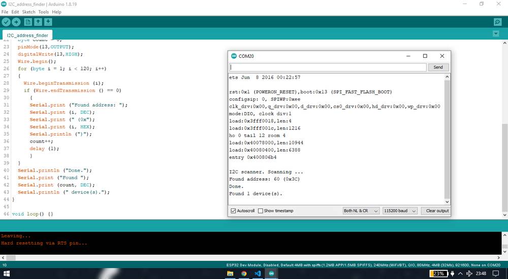
The code to find the unique I2C address,
you can copy the code from here too.
Here is the I2C address shown in the serial monitor,
Here is the sketch i used to display the text in OLED with attiny1614 board,
you can copy the code from here too.
and here is the outcome of the code,
This was an example of I2C communication protocol.
Note that for clicking the screenshot of serial monitor showing the I2C address i used my esp32 board. You ccan find the I2C address of the device
on one board and use the device on another board, since the address you're getting is of the device and not board.
Serial | wired
Serial communication is a form of asynchronus communication where the communicating endpoints' interfaces are not continuously synchronized by
a common clock signal. UART, short for Universal Asynchronous Receiver/Transmitter is a physical circuit in a microcontroller, or a
stand-alone IC whose main purpose is to transmit and receive serial data. Only two wires are needed to transmit data between two UARTs. Data
flows from the Tx pin of the transmitting UART to the Rx pin of the receiving UART.
In the week of input device i made a board with attiny1614 IC where i was reading the data of some input devices into the serial monitor of
the Arduino IDE. After maiking the attiny1614 board, it was much later that i realized that i had not assigned the TX-RX pin to the default
TX-RX pins that are asisgned to the attiny1614 IC. The default TX-RX pin assigned to attiny1614 IC is pin PB2-PB3. While designing the board,
i assigned the TX-RX pin to pin PA4-PA5. I then discoverd that i can still get the readings in the serial monitor using Hardware Serial.
So there are two types when it comes to reading the data serially: Hardware Serial and Software Serial. In the Hardware Serial, you simply write
the code,
Serial.begin(9600);
}
void loop() {
Serial.println("hello world");
}
and upload it to your board and when you open the serial monitor, the board will automatically consider default TX-RX pins assigned to it's IC
to send the data serially and so
you'll see the output in the serial monitor after selecting the correct baud rate,
9600 in my case. Baud rate means the rate at which data/information is transferred so the buad rate in the code and the baud rate in the serial
monitor should match.
Since i had given the wrong connection for the TX-RX pin, i am using my esp32 board to show the serial communication between my board and PC. Here
is the outcome,
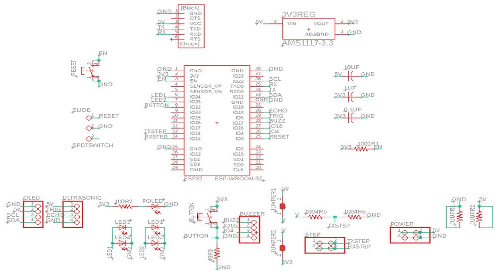
Here is the brief explaination of the connections,
This is how my esp32 board looks like,
This is how my UART serial converter i am using as a prograammer looks like,
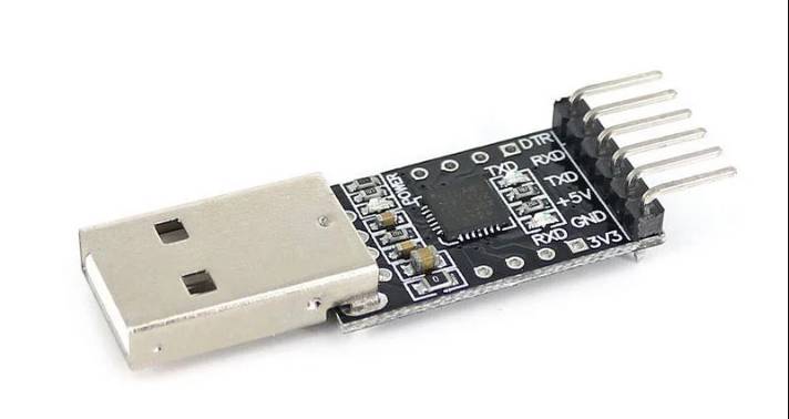
To avoid any confusion, i am naming the GND-VCC-TX-RX pins as serial pins and i am naming UPDI-GND-VCC as UPDI pins.
If you observe, the orientation of the serial pins on my esp32 board(top right) doesn't match the serial pins on my UART serial converter. My
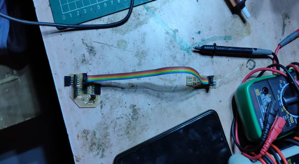
colleague, Vrushabh Zunjunkar, was also using the same UART serial converter so he designed and fabricated a serial converter, which turned out to
be of no use to him so i borrowed it from him and this is how the converter looks like,
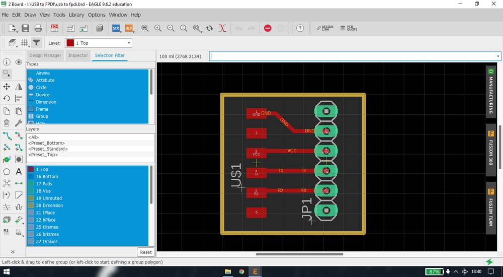
if you see the video above, i have connected the UART serial converter to my PC, connected serial converter to the UART serial converter and connected
the esp32 board with the serial converter so this is the connection of the serial pins:
GND-VCC-TX-RX pin of the UART serial converter is connected to the GND-VCC-TX-RX pin of the serial converter. The GND-VCC-TX-RX pins of the serial
converter is connected to the GND-VCC-RX-TX pins of the esp32 board. So basically the TX-RX pin of the programmer:UART serial converter is connected
to the RX-TX pin of the esp32 and so if you want to serially read the data of the board into your PC, you need to connect the TX-RX pins of
the programmer to the RX-TX pins of the board.
In the software serial, you define the TX-RX pins in your sketch. So you board, instead of considering the default TX-RX pins assigned to it's
IC, will consider the TX-RX pin that you have defined and so you board will send the data through the TX-RX pins that you have deifined.
This is the simple code of printing hello world using software serial,
you can copy the code from here too.
Link for download the software serial library: https://github.com/PaulStoffregen/SoftwareSerial
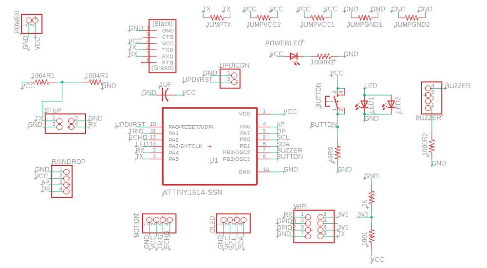
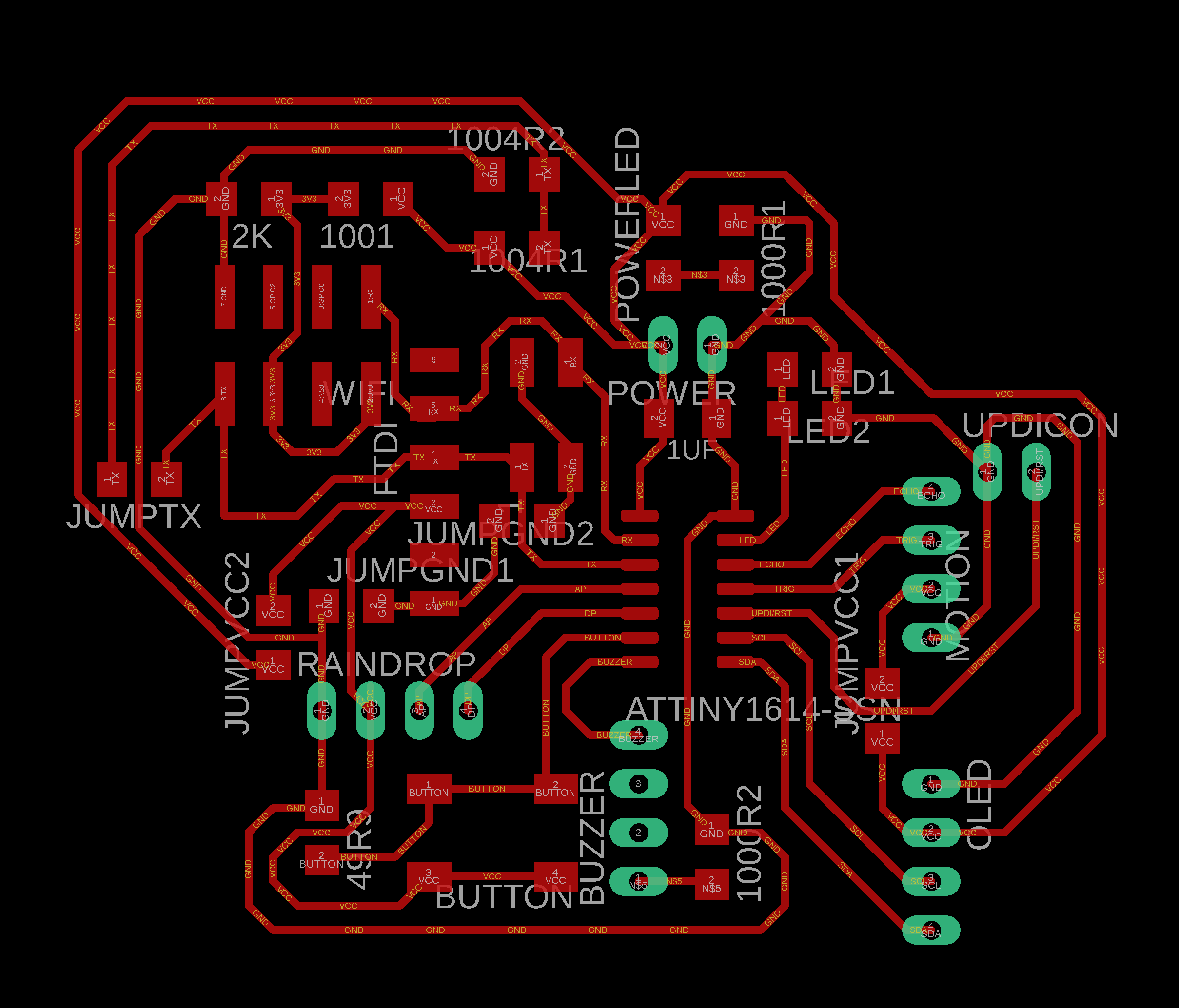
Since i made a mistake in wiring the attiny1614 board, i had to use the software serial. For programming the attiny1614 board, i was using
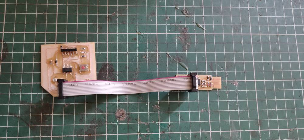
UPDI with FT230XS IC having UPDI pins and to read the data into the serial monitor i was using a Serial UPDI converter. Here is how my attiny1614
board looks like,
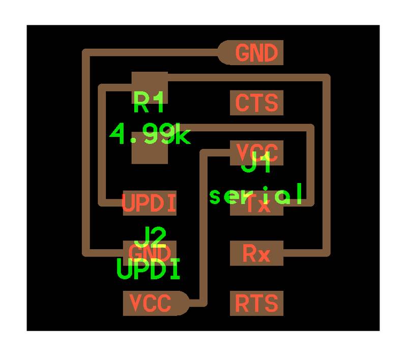
Here is how the serial UPDI converter looks like,
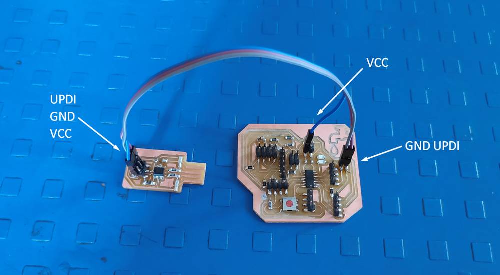
This is the connection i use while uploading the sketch onto the attiny1614 board,
and here is the connection i used while reading the data into the serial monitor,
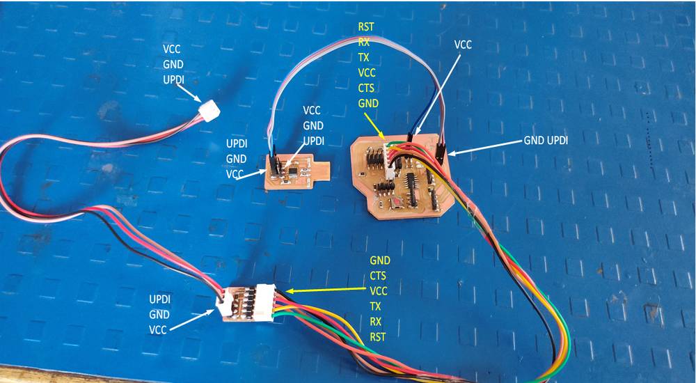
just like in hardware serial, you need to connect the TX-RX pins of the serial UPDI converter to the RX-TX pin of the attiny1614 board. But with
the software serial, you have the advantage of defining the TX-RX pins in the sketch, so you just need to interchange the pin number instead of
changing the wiring.
I was not able to uplaod the code if the RX-TX pins of the UPDI and final project board is connected so i used to dicsonnect the UPDI pins
from the UPDI progreammer while the code was being uplaoded and then connect again to read the data into the serial monitor. You just need to
disconnect the TX-RX communication between the attiny1614 board and the serial UPDI converter.
Here is the outcome,
Serial | wireless
The description mentioned above was the case of wired serial communication where you can get the data from your baord into the serial
monitor. You can get the data from your board to an app via bluetooth or wifi through serial communication too.
In the week of interface and application programming we had to make an application and interface/interact with the board i made. So i made
an app in the MIT app inventor and with that app i controlled an on-board LED through bluetooth module. So here is how i did that,
I first made an app in the MIT app inventor. I have mentioned detailed steps regarding how i made the app in the interface and application
programming tab.
Then i uploaded this code into my attiny1614 board via FT230XS programmer,
you can copy the code from here too.
I took the reference of Adrian's code: http://fabacademy.org/2020/labs/leon/students/adrian-torres/assignments/adrianino/bluetooth/bluetooth.ino
so what this code does is that when you tap on 1, the LED will blink once, if you tap on 2, the LED will blink twice and so on.
after the code is being uploaded, disconnect the programmer from your attiny1614 board and connect the bluetooth module with your attiny1614
board. Here is how you connect the bluetooth module to your board: connect the GND-VCC-RX-TX pins of the bluetooth module with the GND-VCC-TX-RX
pins of the board, and this applies on both, hardware serial and software serial. In my case, since i was using software serial, i connected
the bluetooth module on the RX-TX pins defined in the sketch.
AFter the that you just need to give the power supply to your board. However while recording, i forgot to disconnect the programmer so i was
supplying the power through the programmer.
And this is the outcome,
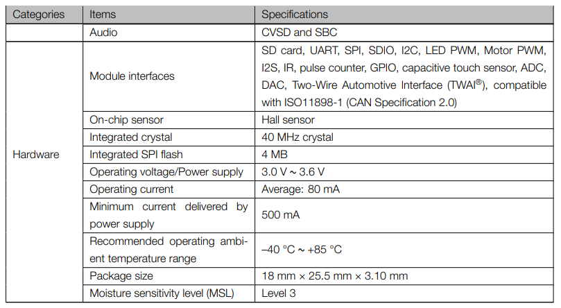
Why esp32?
Initially i wanted to use attiny1614 for my final project but i later realised that the the code for just blinking the LED through wifi using
wifi module esp826601/12e itself was cunsuming 99% of the storage(16KB) and so i decided to switch to esp32 since it has in-built wifi and has
4MB of flash memory(storage),
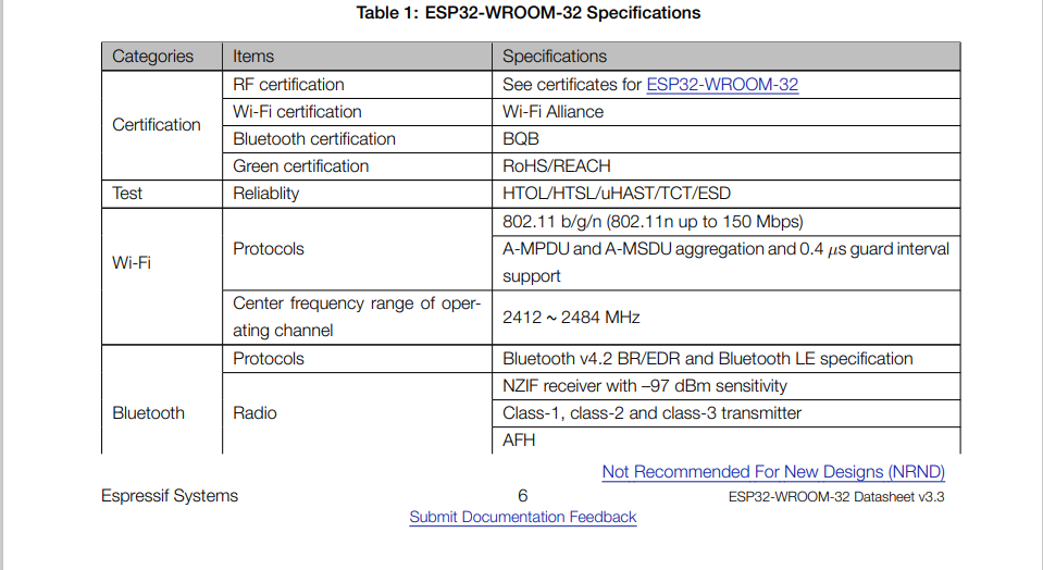
You can download the datasheet of the esp32 from here:
https://www.espressif.com/sites/default/files/documentation/esp32-wroom-32_datasheet_en.pdf
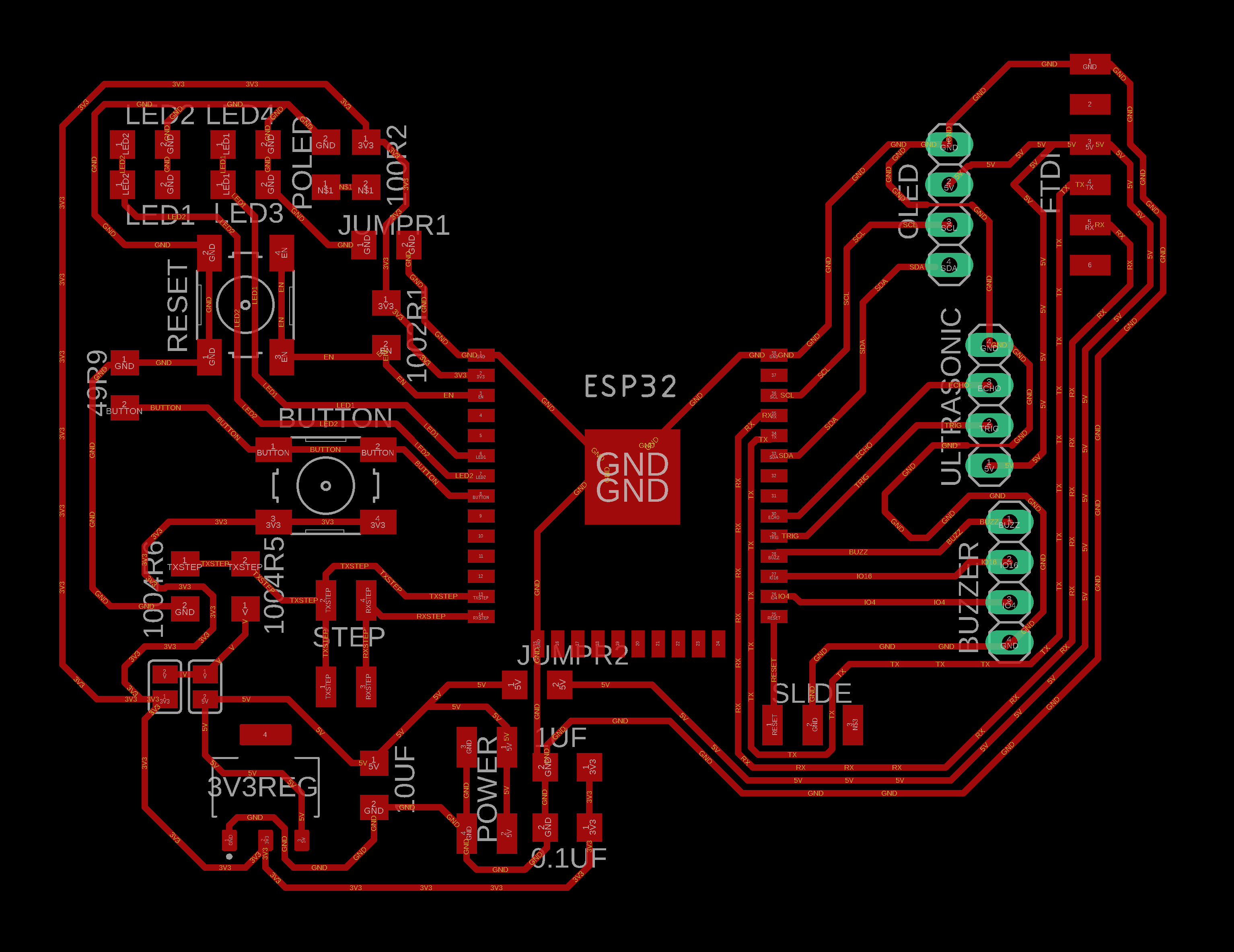
I got better idea of the pin out refering to this image,
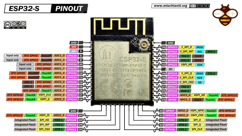
source: https://www.mischianti.org/2021/05/30/esp32-wroom-32-esp32-s-flash-pinout-specs-and-ide-configuration-1/
I learned that GPIO 34, 35, 36, 39 are the input only pins,
if you want to conenct I2C devices, you need to connect the SDA-SCL pin on GPIO21-22,
for programming esp32 you need to use the TX-RX pins assigned on GPIO01-03 and use the same pins for reading the data serially into the
serial monitor
Group assignment
For the group assignment we send the data from one esp32 board to another esp32 board via wifi. You can see the details of the assignment here:
https://fabacademy.org/2022/labs/vigyanashram/groupassig/groupassignment10.html
Drip Irritation by Fenil Chandarana is licensed under Attribution-NonCommercial-NoDerivatives 4.0 International![]()
![]()
![]()
![]()